|
Machines:
A
machine is a device by which a force applied to some point in certain
direction is made available at some point and in some other
direction. The force P applied on the machine is called the effort or
the power while the resistance W overcome by the machine is called
weight or load.
The ratio, load/effort is called
mechanical advantage of a machine. The mechanical advantage should be
greater than one. If, in a machine, the ratio is less than one, it
would be more accurate to call is mechanical disadvantage.

The ratio

is called the velocity ratio of a
machine. The two distances are moved in the same interval of time, so
they are proportional to the velocities of the effort and load.
P◊d1 = W◊d2 in a perfect machine.
or

where d1 and are d2 are
the distances moved by effort P and load W respectively. Hence, in a
perfect machine the mechanical advantage is equal to velocity ratio.
Top
Efficiency
of Machine:
In all
machines some work is always wasted friction. The result of it is
that the work done by the effort in a given time, called total work
or work input (= p ◊ d1) is always greater than the work
done on the load (= W ◊ d2) called useful work or work
output. The difference of the latter from the former = lost work (Pd1-Wd2).
The
ratio

is
called efficiency of machine. It is also defined as the ratio

In
any actual machine the efficiency is always less than one but in a
perfect or ideal machine in where there is no friction at all the
efficiency is equal to unity.
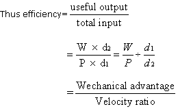
Or
Mechanical advantage = Efficiency ◊ velocity ratio
i.e.
M.A. =Velocity Ratio ◊ η
Top
The
Principle of Work:
In
any actual machine, the useful work obtained is always less than
total work done by the effort. This is because (i) work has to be
done in lifting its parts which have weight, and (ii) because there
is always some internal friction which has to be overcome. A perfect
or ideal machine is one which has no weight and the efficiency of the
machine is unity. Principle of the work is the principle of
conservation of energy i.e., the work done by a machine is equal to
the work done on an ideal or perfect machine. According we have

If W increase, then d2 decrease in the same ratio. Hence
in a machine, whatever is gained in power is lost in speed or
distance.
Uses of a machine:
(i)
This enables one to lift weight or overcome resistances much greater
than one could do unaided as in the case of a pulley-system, a wheel
and axle, a crow bar, a simple screw jack, etc.
(ii)
This enable one to convert a slow motion at some point into a more
rapid motion at some other desired point, viz., a bicycle,. A sewing
machine etc. An opposite effect may also be arranged in practice when
necessary
(iii)
This enable one to use a force acting at a point to be applied at a
more convenient point, as in the case of a poker for stirring up
fire, or to use a force acting at a point in a more convenient
manner, e.g., lifting of a mortar bucket to the top floor by means of
a rope passing over a pulley fixed at the top of the building, the
other end of the rope being pulled down by an agent remaining on the
ground.
(iv)
This enables one to convert a rotatory motion into a linear motion or
vice versa, as in the case of a rack and pinion, etc
(v)
This enables one to convert a to and fro motion into a rotatory
motion or vice versa, e.g., a crank used in the heat engine.
Top
Types
of Simply Machines:
The following
six simple machines represent the types of principles used in making
practical machines.
(1) Pulley.
(2) Inclined plane.
(3) Lever.
(4) Wheel and axle.
(5) Screw and.
(6) Wedge.
Top
(1) Pulley:
A pulley
is a simple machine consists of a grooved wheel, called sheave, over
which a string can pass. The wheel is capable of turning freely about
an axle passing through its centre. The axle is fixed to a frame
work, called the block. The pulley is fixed or movable accordingly as
its block is fixed or movable.
The
Single Fixed Pulley:
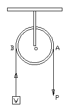
Shows a fixed
pulley in which the block of the pulley is fixed to a rigid support.
The load W is attached to one end of the string passing round the
groove of the pulley and effort P is applied at the other of the
pulley and effort P is applied at the other end. With a perfectly
smooth pulley and a weightless string, the tension of the string will
be the same throughout. Hence the distance through which the load is
raised, is equal to the distance through which the effort descends.
For equilibrium, the moments of P and W about O, the centre of the
wheel, must be equal and opposite.
Or P ◊ AO = W ◊ OB
 AO = OB
 Mechanical
advantage Mechanical
advantage

In
practice, pulleys are not perfectly frictions, and W is always less
than P, that is, the mechanical advantage is always less than 1. But
in spite of this, the arrangement is useful as the operator can use
the weight of this body for raising the land. It is generally used
for raising weights, drawing curtains etc.
Single
Movable pulley:
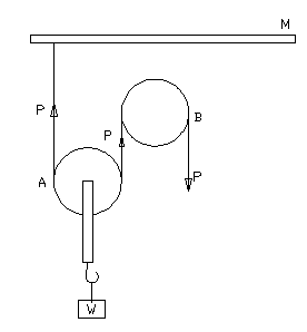
Here one end
of the string passes round the pulley A and is attached to a fixed
support M as shown in. The effort P is applied at the other end of
the rope passing over a fixed pulley B. The load w to be raised is
attached to the block of movable pulley A. The fixed pulley is used
only to apply the power in the downward direction. It is assumed that
the pulleys are frictionless and the tension in the string is the
same at all points and is equal to P. When the strings are vertical
the total upward force is 2d and neglecting the weight of
the pulley, the downward force is W.
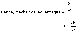
So, for equilibrium W=2P and mechanical advantages

Thus a given effort can raise twice its weight.
If the weight of the pulley is w, then W+w=2P
Or Mechanical advantages = 
The
single movable pulley is much used in cranes. Sails in boats and
flags are raised and lowered with the help of movable pulleys.
Combination
of Pulleys:
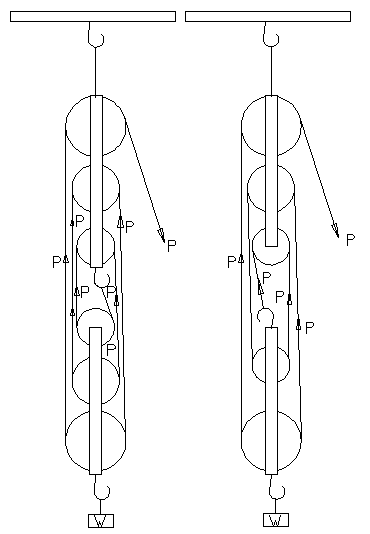
A
combination of pulleys is very often used to secure a mechanical
advantages greater than two. Different systemís having different
mechanical advantages are used for different purposes, but the most
important combination, which is in general use, is given here.
Pulley
Block:
This system consists of two blocks, each containing 2 or 3 pulleys.
The upper block is fixed to a support and the lower one is movable to
which the load W is attached. The string is attached to the upper or
to the lower block, and is then passed round a movable and a fixed
pulley in turn finally passing over a fixed pulley, the effort p being
applied at the free end. It should be noted that when the string is
attached to the upper block, the numbers of wheels in the two blocks
must be the same, but when it is attached to the lower block, the
number of wheels in it will be one less than that in the upper one.
The
tension everywhere round the string is the same and is equal to the
effort P, the pulleys being assumed frictionless. If the number of
position of the string in the lower block be n, the total upward
force on it is nP and this must be equal to the load W supported.
Thus, we have
nP = W + w, when w, is the weight of the lower block.
Top
(2) The
Inclined Plane:
An inclined plane is a smooth rigid flat surface inclined at an angle
to the horizontal. It is used to facilitate the rising of a heavy body
to a certain height by the application of a force which is less than
the weight of the body. The fair-case and the roads on the hills are
typical examples.
Let AB be a plane inclined at an angle θ to the horizontal line
AC and BC is the height of the plane. The body placed on the plane is
acted upon by three forces (i) W, its weight acting vertically
downwards (W=mg), (ii) p, the force or effort, and (iii) R, the
reaction of the plane.
Case. I. Let the force P act upward along the plane.
In
order that the body may be in equilibrium, the sum of the resolved parts
of the forces parallel parts of the forces parallel and perpendicular
to the plane AB are separately equal to zero. Resolving W=mg parallel
and perpendicular to AB, we have mg sin θ perpendicular to AB.
Hence
mg sin θ Ė P = 0;
mg cos θ Ė R = 0
P = mg sin θ:
R = mg cos θ.
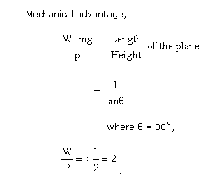
that
is, a body of weight W = mg can be supported by a force P = W/2
acting up the plane.
Top
(3) The Lever:
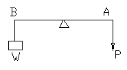
A lever is a simple machine and consists the rest of the lever can
turn. This fixed point is called the fulcrum. The perpendicular
distance between the fulcrum and the point of application of the power
is called the power arm the perpendicular distance between the fulcrum
and the point of application of the weight arm of the lever.
Mechanical
advantage of lever:
Let AB be a
lever with the power P is applied at A and weight W to be lifted is
suspended at B. AF and Bf are the power and weight arms respectively.
The forces act perpendicular to the arms and keep the lever in
equilibrium.
Then, by the principle of moments, we have
P ◊ AF = W ◊ BF
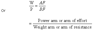
This
is known as the principle of lever.
The
lever is used for pulling weights or overcoming resistance by the
application of force at a suitable point. From the above relation it
is clear that by increasing the length of the power arm, we can lift
a greater weight with the lever.
The
Straight Levers:
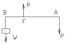
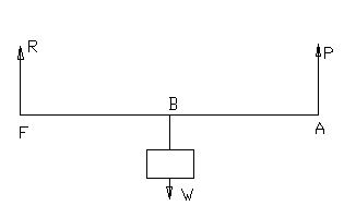
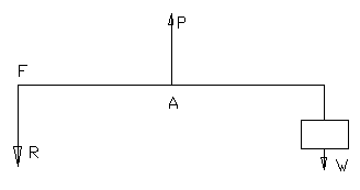
a)
b)
c)
When the
lever is straight and the effort and the weights act perpendicular to
the lever, the following three distinct classes of levers are found
in practice according to the relative positions of A, B and F- the
points of application of the effort, the weight and the fulcrum
respectively. In each of these cases, three parallel forces are
acting on the body. They, therefore, are in the equilibrium
condition. The reaction R at the fulcrum must be equal and opposite
to the resultant of P and W acting at A and B.
A
lever of the first order:
In this case
the effort P and the weight W act on the opposite sides of the
fulcrum F. Here reaction R is the middle force, therefore, P and W
act in the same direction and R in the opposite direction. To lift
the weight, the effort must be applied downwards, and the reaction
acts upwards so that lever presses downwards on the fulcrum. Taking
moments about F, we have


AF
may be either greater, equal or less than BF, so that mechanical
advantages is either or equal or less than unity.
The examples of this type of lever are a poker used to raise the coal
in a grate, handle of water pump, a balance, see-saw, a spade used in
the digging of earth and a bicycle brake. A pair of scissors and a
pair of pincers are examples of double levers of this class.
Second
Order:
In this case,
the weight is placed between the effort and the fulcrum. Hence W is
the middle force. Therefore, P and R act in the same direction and W
in the opposite direction. To lift the weight, the effort must be
applied in the direction. The reaction of the fulcrum also acts
upwards. Taking moments about the fulcrum F, we have,


But
in this class of levers AE is greater than Bf, there force,
mechanical advantage W/P is greater than unity.
Also
W = P + R
Or
R = W- P
The
examples of this class are a crow bar, a wheel barrow, a tin opener,
foot bellows and lifting of a lid of box. A pair of ordinary
nut-crackers and cork squeezer are examples of double levers of this
case.
Third
Order:
Here the effort
P is placed between the weight and the fulcrum as shown in. Since is
the middle force, therefore, W and R act in the same direction and P
in the opposite direction. Also
P = R +W
Or
R = P - W
Thus
to lift weight the effort must be applied upwards, the reaction of
fulcrum acts downwards or lever presses fulcrum upward. Taking
moments about the fulcrum F, we have,


But
in this lever AF is less than Bf, therefore, mechanical advantage is
less than unity. This shows a mechanical disadvantage. This
arrangement gives W a large movements for a small movement of the
effort P, a fact which is just opposite to what happens in the other
two types of levers.
The examples of this type of lever are the forearm, treadle of a
sewing machine in kicking a football and in using a cricket bat. A
fire tongs, a pair of forceps used in a weight box, the upper and
lower jaws of the mouth are examples of double levers of this class.
Top
(4) The
Wheel and Axle:
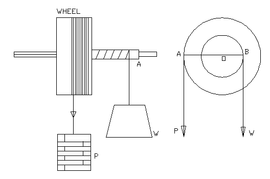
The wheel and
axle is a modification of the lever. It consists of two cylinders of
different diameters capable of turning about a common fixed axis. The
larger cylinder is called the wheel and the smaller the axle. The load
W to be raised is attached to a rope coiled around the wheel in the
opposite direction, so that when the rope round the wheel is
un-coiled, the rope round the axle is coiled up and thereby the
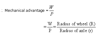
weight is raised. Shows a section where OB is the radius r of the
axle OA the radius R of the wheel. Taking moments about O,
P ◊ OA = W ◊ Ob
Application:
The
windlass by which water is drawn from a well is the same as the wheel
and axle, the crank-handle of which serves the purpose of the wheel.
The capstan used for lifting an anchor in ships, a coffee grinder, a
spanner used to wind a nut, the steering of a motor car, bicycle
pedal etc. are all applications of the wheel and axle.
Top
(5) Screw:
The screw is
a rod usually of some hard metal on the surface of which is cut a
spiral groove. The successive turns of these grooves are separated by
a spiral ridge known as thread. The screw works in a collar or nut
through which a hole is bored, having a groove to fit the thread to
fit groove of the screw. A screw is generally provided with an arm by
means of which it can be rotated. When the screw turns in a fixed
nut, it moves forward or backward in the direction of its length. In
each turn of the screw, the distance moved is equal to the distance
between two connective threads. This distance is called the pith.
Hence, by turning the screw round, it may be used to raise weights or
overcome resistance applied to its ends. To screw press, screw jack,
bolt and nut are some examples of screw.
Mechanical Advantage:
To find the pitch of screw, count the number of grooves
or threads in one centimeter and thus calculate pitch as


when
the screw works without friction.
Screw Jack:
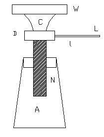
Screw jack as shown in is used for lifting heavy loads
like an automobile in garages and workshops for repair purpose etc.
It
consists of a strong hollow metallic tapering cylinder A having at
the top a hole in the form of a nut N with grooves cut on its inner
side. A square threaded screw moves in this nut and upper end. There
is a loose collar C put on d to avoid rotation of the load W placed
over it when the screw moves. The screw is turned round by a lever
arm of length  or
by a system of cog wheels. The power p is applied at right angles to
the arm. When the lever makes one complete rotation. The screw is
raised vertically through a distance equal to the pitch of
screw. or
by a system of cog wheels. The power p is applied at right angles to
the arm. When the lever makes one complete rotation. The screw is
raised vertically through a distance equal to the pitch of
screw.

By using a system of cog wheel, the load is raised through a distance
equal to the pitch of the screw when lever is given n rotations, then

Winch
of Lifting Crab:
This machine is used for lifting comparatively
heavy loads by means of a small effort such as can be exerted by
hand. It is used when greater velocity ratio and also mechanical
advantage is required than can be conveniently obtained with a wheel
and axle, in which convenient length of handle is limited by the
range of a manís arm and the diameter of the drum by the
consideration of holding all the rope necessary for a given lift.
Single
Purchase Crab:
It consists of two stands A1
and A2. Connected rigidly together by the three stays B1,
B2 and B3 and having bearings for the spindle B
and the drum D. On the spindle C is keyed the pinion E, which gears
with and drives the larger spur wheel F on the drum D. The ends of C
are squared to receive handles H, on the ends of which the effort is
applied. The load is lifted by a rope which is coiled round the drum
D.
Velocity Ratio. Let,
R=radius or a length of handle,
T1=number
of teeth in pinion,
T3=number of teeth in wheel,
r=radius of drum.
Now in one revolution of the of handle we have-
Motion of effort = 2πR
Motion of pitch circle of pinion
= 1 revolution
=T1p (P=pitch)
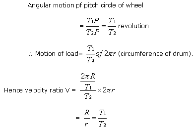
which
is the product of the velocity ratio of wheel and axle and a pair of
spur wheels of given numbers of teeth.
Top
(6) Wedge:
A wedge is a
simple machine consisting of a solid block of metal or wood shaped as
an inclined plane. A small dividing force P applied to the wedge
results in a much larger splitting or separating force. It is
commonly used for raising heavy bodies for widening a gap, for
breaking strong cover joints etc.
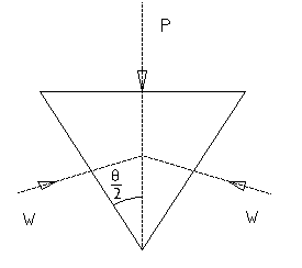
A
double wedge is shown in, being used for widening a gap. The
separating forces generated product equal reaction W, W at the edges
of the gap. The forces, P, W, W can be represented by a triangle shown
in, neglecting friction.
Hence
P = 2w sin θ/2
And
M.A. = 
The
action of an axe, or a nail knife may to be treated as that of a
combination of two wedges.
Top
|